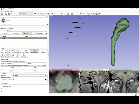
Segment editor
This is a module is for specifying segments (structures of interest) in 2D/3D/4D images. Some of the tools mimic a painting interface like photoshop or gimp, but work on 3D arrays of voxels rather than on 2D pixels. The module offers editing of overlapping segments, display in both 2D and 3D views, fine-grained visualization options, editing in 3D views, create segmentation by interpolating or extrapolating segmentation on a few slices, editing on slices in any orientation.
Segment Editor does not edit labelmap volumes or models, but segmentations can be easily converted to/from labelmap volumes and models using the Import/Export section of Segmentations module.

Keyboard shortcuts
The following keyboard shortcuts are active when you are in the Editor module. They are intended to allow two-handed editing, where on hand is on the mouse and the other hand uses the keyboard to switch modes.
| Key | Operation |
|---|---|
left arrow |
move to previous slice |
right arrow |
move to next slice |
Shift + mouse move |
scroll slices to mouse location |
Ctrl + mouse wheel |
zoom image in/out |
q |
select previous segment |
w |
select next segment |
z |
undo |
y |
redo |
esc |
unselect effect |
space |
toggle between last two active effects |
1, 2, … 0 |
select effect (1-10) |
Shift + 1, 2, … 0 |
select effect (11-20) |
i |
toggle masking by intensity range |
Tutorials
Panels and their use
- Segmentation: Choose the segmentation to edit
- Master volume: Choose the volume to segment. The master volume that is selected the very first time after the segmentation is created is used to determine the segmentation’s labelmap representation geometry (extent, resolution, axis directions, origin). The master volume is used by all editor effects that uses intensity of the segmented volume (e.g., thresholding, level tracing). The master volume can be changed at any time during the segmentation process. Note: changing the master volume does not affect the segmentation’s labelmap representation geometry. To make changes to the geometry (make the extent larger, the resolution finer, etc.) click “Specify geometry” button next to the master volume selector, select a “Source geometry” node that will be used as a basis for the new geometry, adjust parameters, and click OK. To specify an arbitrary extens, an ROI (region of interest) node can be created and selected as source geometry.
- Add segment: Add a new segment to the segmentation and select it.
- Remove segment: Select the segment you would like to delete then click Remove segment to delete from the segmentation.
- Create Surface: Display your segmentation in the 3D Viewer. This is a toggle button. When turned on the surface is created and updated automatically as the user is segmenting. When turned off, the conversion is not ongoing so the segmentation process is faster. To change surface creation parameters: go to Segmentations module, click Update button in Closed surface row in Representations section, click Binary labelmap -> Closed surface line, double-click on value column to edit a conversion parameter value. Setting Smoothing factor to 0 disables smoothing, making updates much faster. Set Smoothing factor to 0.1 for weak smoothing and 0.5 or larger for stronger smoothing.
- Segments table: Displays list of all segments.
- Eye icon: Toggle segment’s visibility. To customize visualization: either open the slice view controls (click on push-pint and double-arrow icons at the top of a slice viewer) or go to Segmentations module.
- Color swatch: set color and assign segment to standardized terminology.
- Effects: Select the desired effect here. See below for more information about each effect.
- Options: Options for the selected effect will be displayed here.
- Undo/Redo: The module saves state of segmentation before each effect is applied. This is useful for experimentation and error correction. By default the last 10 states are remembered.
- Masking: These options allow you to define the editable areas and whether or not certain segments can be overwritten.
- Editable area: Changes will be limited to the selected area. This can be used for drawing inside a specific region or split a segment into multiple segments.
- Editable intensity range: Changes wil be limited to areas where the master volume’s voxels are in the selected intensity range. It is useful when locally an intensity threshold separates well between different regions. Intensity range can be previewed by using Threshold effect.
- Modify other segments: Select which segments will be overwritten rather than overlapped.
- Overwrite all: Segment will not overlap (default).
- Overwrite visible: Visible segments will not overlap with each other. Hidden segments will not be overwritten by changes done to visible segments.
- Allow overlap: Changing one segment will not change any other.
Effects
Effects operate either by clicking the Apply button in the effect options section or by clicking and/or dragging in slice or 3D views.
 Paint
- Pick the radius (in millimeters) of the brush to apply
- Left click to apply single circle
- Left click and drag to fill a region
- A trace of circles is left which are applied when the mouse button is released
- Sphere mode applies the radius to slices above and below the current slice.
| Key | Operation |
|---|---|
Shift + mouse wheel |
increase/decrease brush size |
- |
shrink brush radius by 20% |
+ |
grow brush |
 Draw
Draw
- Left click to lay individual points of an outline
- Left drag to lay down a continuous line of points
- Right click to apply segment
| Key | Operation |
|---|---|
x |
delete the last point added |
a |
apply segment |
 Erase
Same as the Paint effect, but the highlighted regions are removed from the selected segment instead of added.
If Masking / Editable area is set to a specific segment then the highlighted region is removed from selected segment and added to the masking segment. This is useful when a part of a segment has to be separated into another segment.
| Key | Operation |
|---|---|
Shift + mouse wheel |
increase/decrease brush size |
- |
shrink brush radius by 20% |
+ |
grow brush radius by 20% |
 Level Tracing
- Moving the mouse defines an outline where the pixels all have the same background value as the current background pixel
- Clicking the left mouse button applies that outline to the label map
 Grow from seeds
Draw segment inside each anatomical structure. This method will start from these “seeds” and grow them to achieve complete segmentation.
- Initialize: Click this button after initial segmentation is completed (by using other editor effects). Initial computation may take more time than subsequent updates. Master volume and auto-complete method will be locked after initialization, therefore if either of these have to be changed then click Cancel and initialize again.
- Update: Update completed segmentation based on changed inputs.
- Auto-update: activate this option to automatically updating result preview when segmentation is changed.
- Cancel: Remove result preview. Seeds are kept unchanged, so parameters can be changed and segmentation can be restarted by clicking Initialize.
- Apply: Overwrite seeds segments with previewed results.
Notes:
- Only visible segments are used by this effect.
- At least two segments are required.
- If a part of a segment is erased or painting is removed using Undo (and not overwritten by another segment) then it is recommended to cancel and initialize. The reason is that effect of adding more information (painting more seeds) can be propagated to the complete segmentation, but removing information (removing some seed regions) will not change the complete segmentation.
- The method uses grow-cut algorithm: Liangjia Zhu, Ivan Kolesov, Yi Gao, Ron Kikinis, Allen Tannenbaum. An Effective Interactive Medical Image Segmentation Method Using Fast GrowCut, International Conference on Medical Image Computing and Computer Assisted Intervention (MICCAI), Interactive Medical Image Computing Workshop, 2014.
 Fill between slices
Create complete segmentation on selected slices using any editor effect. You can skip any number of slices between segmented slices. This method will fill the skipped slices by interpolating between segmented slices.
- Initialize: Click this button after initial segmentation is completed (by using other editor effects). Initial computation may take more time than subsequent updates. Master volume and auto-complete method will be locked after initialization, therefore if either of these have to be changed then click Cancel and initialize again.
- Update: Update completed segmentation based on changed inputs.
- Auto-update: activate this option to automatically updating result preview when segmentation is changed.
- Cancel: Remove result preview. Seeds are kept unchanged, so parameters can be changed and segmentation can be restarted by clicking Initialize.
- Apply: Overwrite seeds segments with previewed results.
Notes:
- Only visible segments are used by this effect.
- The method does not use the master volume, only the shape of the specified segments.
- The method uses ND morphological contour interpolation algorithm. See details here: http://insight-journal.org/browse/publication/977
 Threshold
Use Threshold to determine a threshold range and save results to selected segment or use it as Editable intensity range.
 Margin
Grows or shrinks the selected segment by the specified margin.
 Smoothing
Smoothes selected labelmap or all labelmaps (only for Joint smoothing method).
By clicking Apply button, the entire segmentation is smoothed.
To smooth a specific region, left click and drag in any slice or 3D view. Same smoothing method and strength is used as for the whole-segmentation mode (size of the brush does not affect smoothing strength, just makes it easier to designate a larger region).
Available methods:
- Median: removes small extrusions and fills small gaps while keeps smooth contours mostly unchanged. Applied to selected segment only.
- Opening: removes extrusions smaller than the specified kernel size. Does not add anything to the segment. Applied to selected segment only.
- Closing: fills sharp corners and holes smaller than the specified kernel size. Does not remove anything from the segment. Applied to selected segment only.
- Gaussian: smoothes all details. Strong smoothing as achievable, but tends to shrink the segment. Applied to selected segment only.
- Joint smoothing: smoothes multiple segments at once, preserving watertight interface between them. If segments overlap, segment higher in the segments table will have priority. Applied to all visible segments.
 Scissors
Clip segments to the specified region or fill regions of a segment (typically used with masking). Regions can be drawn on both slice view or 3D views.
- Left click to start drawing (free-form or rubber band circle or rectangle)
- Release button to apply
 Islands
Use this tool to create a unique segment for each connected region of the selected segment. Connected regions are defined as groups of pixels which touch each other but are surrounded by zero valued voxels.
- Fully connected: If checked then only voxels that share a face are counted as connected; if unchecked then voxels that touch at an edge or a corner are considered connected.
- Minimum size: All regions that have less than this number of voxels will be deleted.
 Logical operators
Apply Boolean operators to selected segment or combine segments.
 Mask volume
Blank out inside/outside of a segment in a volume or create a binary mask. Result can be saved into a new volume or overwrite the input volume. This is useful for removing irrelevant details from an image (for example remove patient table; or crop the volume to arbitrary shape for volume rendering) or create masks for image processing operations (such as registration or intensity correction).
- Fill inside: set all voxels of the selected volume to the specified value inside the selected segment
- Fill outside: set all voxels of the selected volume to the specified value outside the selected segment
- Fill inside and outside: create a binary labelmap volume as output. Most image procesing operations require background (outside, ignored) region to be filled with 0 value.
Tips
- A large radius paint brush with threshold painting is often a very fast way to segment anatomy that is consistently brighter or darker than the surrounding region, but partially connected to similar nearby structures (this happens a lot).
- Use the slice viewer menus to control the label map opacity and display mode (to show outlines only or full volume).
Frequently asked questions
Cannot paint outside some boundaries
When you create a segmentation, internal labelmap geometry (extent, origin, spacing, axis directions) is determined from the master volume that you choose first. You cannot paint outside this extent.
If you want to extend the segmentation to a larger region then you need to modify segmentation’s geometry using “Specify geometry” button.
Segmentation is not accurate enough
If details cannot be accurately depicted during segmentation or the exported surface has non-negligible errors (there are gaps or overlap between segments), then it is necessary to reduce the segmentation’s spacing (more accurately: spacing of the internal binary labelmap representation in the segmentation node). Spacing is also known as voxel size or may be referred to as resoution (which is inverse of spacing - higher resolution means smaller spacing).
As a general rule, segmentation’s spacing needs to be 2-5x smaller than the size of the smallest relevant detail or the maximum acceptable surface error in the generated surface.
By default, segmentation’s spacing is set from the master volume that is selected first after the segmentation is created. If the first selected master volume’s resolution is not sufficient or highly anisotropic (spacing value is not the same along the 3 axes) then one of the followings is recommended:
- Option A. Crop and resample the input volume using Crop volume module before starting segmentation. Make spacing smaller (small enough to represent all details but not too small to slow things down and consume too much memory) and isotropic by reducing Spacing scale and enabling Isotropic spacing. Also adjust the region of interest to crop the volume to minimum necessary size to minimize memory usage and make editing faster.
- Option B. Click Specify geometry button in Segment Editor any time to specify smaller spacing. After this smooth segments using Smoothing effect. Joint smoothing method is recommended as it can smooth all the segments at once and it preserves boundaries between segments. Joint smoothing flattens all the processed segments into one layer, so if the segentation contains overlapping segments then segment in several steps, in each step only show a set of non-overlapping segments (or use any of the other smoothing methods, which only operate on the selected segment).
Generated surface contains step artifacts
If 3D surface generated from the segmentation contains step artifacts (looks “blocky”) then it is necessary to increase smoothing and/or reduce segmentation’s spacing.
Users need to choose between having smooth surface vs. no gaps or overlap between segments. It is impossible to have both. To achieve the desired results, there are two parameters to control: segmentation’s spacing and surface smoothing factor:
- Choose spacing that allows accurate segmentation (see Segmentation is not accurate enough section above)
- Choose smoothing value that removes staircase artifacts but still preserves all details that you are interested in.
- If you find that the surface smoothing value that is high enough to remove staircase artifacts also removes relevant details then further reduce spacing.
Paint affects neighbor slices or stripes appear in painted segments
Segment Editor allows editing of segmentation on slices of arbitrary orientation. However, since edited segments are stored as binary labelmaps, “striping” artifacts may appear on thin segments or near boundary of any segments. See Oblique segmentation segmentation recipe for more details and instructions on how to deal with these artifacts.
Limitations
- Threshold will not work with non-scalar volume background volumes.
- Mouse wheel can be used to move slice through volume, but on some platforms (mac) it may move more than one slice at a time.
Information for Developers
See examples for creating and modifying segmentation nodes and using segment editor effects from your own modules in Slicer script repository
Contributors
Authors:
- Csaba Pinter (PerkLab, Queen’s University)
- Andras Lasso (PerkLab, Queen’s University)
- Kyle Sunderland (PerkLab, Queen’s University)
- Steve Pieper (Isomics Inc.)
- Wendy Plesniak (SPL, BWH)
- Ron Kikinis (SPL, BWH)
- Jim Miller (GE)
Acknowledgements
This module is partly funded by an Applied Cancer Research Unit of Cancer Care Ontario with funds provided by the Ministry of Health and Long-Term Care and the Ontario Consortium for Adaptive Interventions in Radiation Oncology (OCAIRO) to provide free, open-source toolset for radiotherapy and related image-guided interventions.
The work is part of the National Alliance for Medical Image Computing <http://www.na-mic.org/>_ (NA-MIC), funded by the National Institutes of Health through the NIH Roadmap for Medical Research, Grant U54 EB005149.
![]()
![]()
![]()
![]()
![]()