User Interface
Application overview
Slicer stores all loaded data in a data repository, called the “scene” (or Slicer scene or MRML scene). Each data set, such as an image volume, surface model, or point set, is represented in the scene as a “node”.
Slicer provides a large number “modules”, each implementing a specific set of functions for creating or manipulating data in the scene. Modules typically do not interact with each other directly: they just all operate on the data nodes in the scene. Slicer package contains over 100 built-in modules and additional modules can be installed by using the Extensions Manager.

Module Panel
This panel (located by default on the left side of the application main window) displays all the options and features that the current module offers to the user. Current module can be selected using the Module Selection toolbar.
Data Probe
Data Probe is located at the bottom of the module panel. It displays information about view content at the position of the mouse pointer:
Slice view information (displayed when the mouse is over a slice view):
Slice view name:
Red,Green,Yellow, etc.Anatomical position: three coordinate values, prefixed with
R/L(right/left),A/P(anterior/posterior),S/I(superior/inferior). The origin - (0,0,0) position - was chosen by the imaging technologist when the image was created. For example(R 17.6, P 35.3, S 12.1)for a clinical image means that the current position is 17.6mm to the right from the origin, 35.3mm towards posterior, 12.1mm superior from the origin.View orientation:
Axial,Sagittal,Coronalfor standard anatomical orientations, andReformatfor any other orientation.Slice spacing: distance between slices in this orientation. For a clinical image
Sp: 2.5means that slices are 2.5mm distance from each other.
Volume layer information: three lines, one for each volume layer
Layer type:
L(label),F(foreground),B(background).Volume name, or
Noneif no volume is selected for that layer.Volume voxel (IJK) coordinates.
Voxel value. For label volumes the label name corresponding to the voxel value is also displayed.
Segmentation information: for each segmentation visible at that position
Layer type:
S(segmentation)Segmentation name.
Segment names. Multiple segment names are listed if multiple segments are displayed at that position (the segments overlap).
Views
Slicer displays data in various views. The user can choose between a number of predefined layouts, which may contain slice, 3D, chart, and table views.
The Layout Toolbar provides a drop-down menu of layouts useful for many types of studies. When Slicer is exited normally, the selected layout is saved and restored next time the application is started.
Toolbar
Toolbar provides quick access to commonly used functions. Individual toolbar panels can be shown/hidden using menu: View / Toolbars section.
Module Selection toolbar is used for selecting the currently active “module”. The toolbar provides options for searching for module names (Ctrl + f or click on magnify glass icon) or selecting from a menu. Module history dropdown button shows the list of recently used modules. Arrow buttons can be used for going back to/returning from previously used module.

Favorite modules toolbar contains a list of most frequently used modules. The list can be customized using menu: Edit / Application settings / Modules / Favorite Modules. Drag-and-drop modules from the Modules list to the Favorite Modules list to add a module.
Status bar
This panel may display application status, such as current operation in progress. Clicking the little X icons displays the Error Log window.
Review loaded data
Data available in Slicer can be reviewed in the Data module, which can be found on the toolbar or the modules list  . More details about the module can be found on the Slicer wiki.
The Data module’s default Subject hierarchy tab can show the datasets in a tree hierarchy, arranged as patient/study/series as typical in DICOM, or any other folder structure:

The Subject hierarchy view contains numerous built-in functions for all types of data. These functions can be accessed by right-clicking the node in the tree. The list of actions differs for each data type, so it is useful to explore the options.
Medical imaging data comes in various forms and representations, which may confuse people just starting in the field. The following diagram gives a brief overview about the most typical data types encountered when using Slicer, especially in a workflow that involves segmentation.

Selecting displayed data
Data module’s Subject hierarchy tab shows all data sets in the scene. Click the “eye” icon to show/hide an item in all views. Drag-and-drop an item into a view to show it in that view.

Multiple items can be selected in the subject hierarchy tree using Ctrl-Left-Click or Shift-Left-Click and dragged at once into selected view. If two volumes are dragged into a view at the same time then they will be both shown, blended together.
If a view is displayed only in selected views, you can right-click on the item and select “Show in all views” to quickly show in all views.
If view link is enabled for a slice view then dragging a volume to any of the views will show the volume in all the views in that group.
Display options can be adjusted by right-clicking the eye icon in the display column of the tree. Note that these options are different from options that are offered when right-clicking on the “Node” or “Transform” column in the tree.

For volumes, display options include:
Reset field of view on show: if enabled, then showing a volume makes adjust views to show the volume in the center, filling the field of view.
Reset view orientation on show: if enabled, then showing a volume makes the slice views aligned with the volume axes.
Interacting with views
View Cross-Reference
Holding down the Shift key while moving the mouse in any slice or 3D view will cause the Crosshair to move to the selected position in all views. By default, when the Crosshair is moved in any views, all slice views are scrolled to the same RAS position indexed by the mouse. This feature is useful when inspecting.
To show/hide the Crosshair position, click crosshair icon
 .
.
To customize behavior and appearance of the Crosshair, click the “down arrow” button on the right side of the crosshair icon.
Mouse Modes
Slicer has multiple mouse modes: Transform (which allows interactive rotate, translate and zoom operations), Window/Level to adjust brightness/contrast of the image volumes, and Place (which permits objects to be interactively placed in slice and 3D views).

The toolbar icons that switch between these mouse modes are shown from left to right above, respectively. Place Point List is the default place option as shown above; options to place other nodes such as Ruler and Region of Interest Widgets are also available from the drop-down Place Mode menu.
Note
Transform mode is the default interaction mode. By default, Place mode persists for one “place” operation after the Place Mode icon is selected, and then the mode switches back to Transform. Place mode can be made persistent (useful for placing multiple control points) by checking the Persistent checkbox shown rightmost in the Mouse Mode Toolbar.
Adjusting image window/level
Medical images typically contain thousands of gray levels, but regular computer displays can display only 256 gray levels, and the human eye also has limitation in what minimum contrast difference it can notice (see Kimpe 2007 for more specific information). Therefore, medical images are displayed with adjustable brightness/contrast (window/level).
By default 3D Slicer uses window/level setting that is specified in the DICOM file. If it is not available then window/level is set to contain the entire intensity range of the image (except top/bottom 0.1%, calculated using percentiles, to not let a very thin tail of the intensity distribution to decrease the image contrast too much).
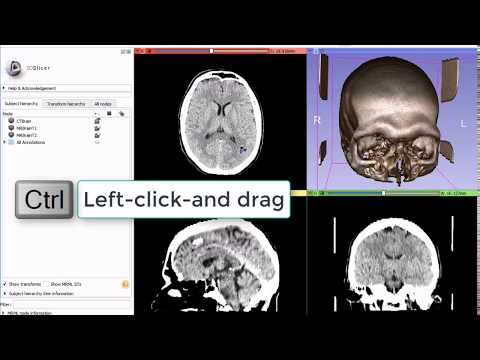
Window/level can be manually adjusted anytime by clicking on “Adjust window/level” button on the toolbar then left-click-and-drag in any of the slice viewers. Optimal window/level can be computed for a chosen area by lef-click-and-dragging while holding down Ctrl key.
Additional window/level options, presets, intensity histogram, automatic adjustments are available in Display section of Volumes module. Presets are also available in the context menu of the Slice views. You can reset to the automatically calculated window/level settings using the context menu or by using Ctrl + left-double-click on the Slice view.
3D View
Displays a rendered 3D view of the scene along with visual references to specify orientation and scale.
Default orientation axes: A = anterior, P = posterior, R = right, L = left, S = superior and I = inferior.

3D View Controls: The blue bar across any 3D View shows a pushpin icon on its left. When the mouse rolls over this icon, a panel for configuring the 3D View is displayed. The panel is hidden when the mouse moves away. For persistent display of this panel, just click the pushpin icon.
Center 3D view (small square) centers the slice on the currently visible 3D view content and all loaded volumes (even if volumes that are not visible). The field of view (zoom factor) is not adjusted, therefore it may be necessary to zoom in/out to see all objects. To reset the center and field of view at the same time, click in the 3D view and hit r key.
Maximize view / Restore view layout temporarily maximizes the selected view / restores the full view layout.
Viewpoint direction switches orientation of the view between standard directions. Clicking on Left, Right, Anterior, Posterior, Superior, Inferior button will make the 3D content viewed from that direction.
View link button synchronizes properties across 3D views (viewpoint position, direction, ruler, orientation marker, etc. settings).
Orthographic/perspective rendering mode toggle. Orthographic mode (parallel projection) is useful for assessing size, because displayed object size does not depend on distance from the viewpoint. Perspective mode provides better depth perception, because objects that are closer appear larger.
Ruler controls display of ruler. Only available in orthographic rendering mode.
Stereo viewing enables stereoscopic display. Red/blue and anaglyph modes just require inexpensive red/blue colored glasses. Other modes require special 3D display hardware. Note that SlicerVirtualReality extension offers superior stereo viewing and interaction experience, with fully immersive 3D visualization by a single click of a button, and rich interaction with objects in the scene using 3D controllers.
More options (…)
Use depth peeling must be enabled for correct rendering of semi-transparent surfaces (in models, markups, etc). It may make rendering updates slightly slower and artifacts when volume rendering is used in the view.
Show/Hide frames per second (FPS) displays rendering speed in the corner of the view.
Orientation Marker controls display of human, cube, etc in lower right corner.
Visibility options controls visibility of view background color and displayed components.
Spin continuously spins the view around.
Rock continuously rocks the view left-to-right.
Zoom in/out slightly zooms in/out the view. Convenient buttons for touchscreens.
Tilt Lock can be toggled using
Ctrl+bkeyboard shortcut. In tilt lock mode 3D view rotation is restricted to the azimuth axis (left-right direction) by disabling rotation around elevation axis (up-down direction).
Ambient shadows
Shadows visibility: if enabled then ambient shadows are displayed to improve depth perception
Size scale (default: 0): Size of features to be emphasized by shadows. Lower values emphasize surface unevenness (bumps and depressions). Higher size scale makes larger regions that are much farther much darker. The optimal value can be determined by adjusting the value starting from the highest value gradually until regions that are behind objects appear darker. Very high values (1.5 to 3.0) may make the entire image appear darker, therefore it is important to go below this range, typically down to about 0.5 to 1.5.
Intensity scale: (default: 1): Intensity of darkening by shadows. Increase the value to make shadows darker.
Intensity shift: (default: 0): Minimum amount of occlusion required for visible darkening by shadows. It is usually only necessary to increase this value if the intensity scale is increased, which makes the entire image somewhat darker. In this case, increasing the intensity shift can compensate the overall darkening.
Volume opacity threshold (0% to 100%; default: 25%): This value only affects volume rendering. Voxels that have opacity above this value will cast shadows. Choosing too low value results in dark artifacts in regions that have very low opacity. Choosing too high value results artifacts near opaque regions that have somewhat lower opacity value.
Examples:

Note
Default ambient shadows settings can be chosen in the application menu (Edit / Application Settings / Views / 3D viewer defaults).
Slice View
Three default slice views are provided (with Red, Yellow and Green colored bars) in which Axial, Sagittal, Coronal or Oblique 2D slices of volume images can be displayed. Additional generic slice views have a grey colored bar and an identifying number in their upper left corner.

Slice View Controls: The colored bar across any slice view shows a pushpin icon on its left (Show view controls). When the mouse rolls over this icon, a panel for configuring the slice view is displayed. The panel is hidden when the mouse moves away. For persistent display of this panel, just click the pushpin icon. For more options, click the double-arrow icon (Show all options).
View Controllers module provides an alternate way of displaying these controllers in the Module Panel.
Reset field of view (small square) centers the slice on the current background volume
Show in 3D “eye” button in the top row can show the current slice in 3D views. Drop-down menu of the button contains advanced options to customize how this slice is rendered: “…match volume” means that the properties are taken from the full volume, while “…match 2D” means that the properties are copied from the current slice view (for example, copies zoom and pan position). Typically these differences are subtle and the settings can be left at default.
Slice orientation displays allows you to choose the orientation for this slice view.
Reformat allows interactive manipulation of the slice orientation.
Slice offset slider allows slicing through the volume. Step size is set to the background volume’s spacing by default but can be modified by clicking on “Spacing and field of view” button. The label next to the offset value (e.g.,
S,L,A,IL,IRP) reflects the slice normal direction. If the offset slider moved to the right then the slice moves in this normal direction. If the slice normal direction is not aligned with an axis then the label contains a combination of directions, with the order of axes reflecting the dominance of the axis. For example, if the plane normal points to anterior and slightly left then the label isAL, while if the plane normal mostly left and slightly anterior then the label isLA.Blending mode specifies how foreground and background layers are mixed.
Spacing and field of view Spacing defines the increment for the slice offset slider. Field of view sets the zoom level for the slice.
Rotate to volume plane changes the orientation of the slice to match the closest acquisition orientation of the displayed volume.
Orientation Marker controls display of human, cube, etc in lower right corner.
Ruler controls display of ruler in slice view.
View link button synchronizes properties of views in the same view group, such as foreground/background/label volume selection, foreground/label volume opacity, zoom factor.
For parallel views (i.e., that are set to the same orientation,OD such as
axial), the view center position is synchronized as well.Long-click on the button exposes hot-linked option, which controls when properties are synchronized (immediately or when the mouse button is released).
A view group typically consists of 3 orthogonal views (e.g., in
Four-Upview,R,G,Y, views are in the same group). In layouts that contain multiple triplets of slice views, each triplet forms a separate group (e.g., inThree over threelayout there are two view groups, one group isR,G,Y, the other groups isR+,G+,Y+`).
Layer visibility “eye” buttons and Layer opacity spinboxes control visibility of segmentations and volumes in the slice view.
Foreground volume opacity slider allows fading between foreground and background volumes.
Interpolation allows displaying voxel values without interpolation. Recommended to keep interpolation enabled, and only disable it for testing and troubleshooting.
Node selectors are used to choose which background, foreground, and labelmap volumes and segmentations to display in this slice view. Note: multiple segmentations can be displayed in a slice view, but slice view controls only allow adjusting visibility of the currently selected segmentation node.
Removed in version 5.10:
Lightbox feature to select a mosaic (a.k.a. contact sheet) view was removed. Instead the Lightbox image columns option provided by the Screen Capture module may be used.
Mouse & Keyboard Shortcuts
Alternate macOS Keybindings
When using shortcuts on macOS, replace the following keys with their corresponding macOS version.
| Key | macOS Key |
|---|---|
Ctrl |
Command / ⌘ |
Alt |
Option / ⌥ / Alt |
Generic shortcuts
| Shortcut | Operation |
|---|---|
Ctrl + f |
find module by name (hit Enter to select) |
Ctrl + o |
add data from file |
Ctrl + s |
save data to files |
Ctrl + w |
close scene |
Ctrl + 0 |
show Error Log |
Ctrl + 1 |
show Application Help |
Ctrl + 2 |
show Application Settings |
Ctrl + 3 / Ctrl + ` |
show/hide Python Console |
Ctrl + 4 |
show Extensions Manager |
Ctrl + 5 |
show/hide Module Panel |
Ctrl + h |
open default startup module (configurable in Application Settings) |
Slice views
The following shortcuts are available when a slice view is active. To
activate a view, click inside the view: if you do not want to change
anything in the view, just activate it then do right-click without
moving the mouse. Note that simply hovering over the mouse over a slice
view will not activate the view.
| Shortcut | Operation |
|---|---|
right-click + drag up/down |
zoom image in/out (Alt optional, useful during point placement) |
Ctrl + mouse wheel |
zoom image in/out |
middle-click + drag |
pan (translate) view (Alt optional, useful during point placement) |
Shift + left-click + drag |
pan (translate) view (Alt optional, useful during point placement) |
left arrow / right arrow |
move to previous/next slice |
b / f |
move to previous/next slice |
Shift + mouse move |
move crosshair in all views |
Ctrl + Alt + left-click + drag |
rotate slice intersection of other views (Slice intersections must be enabled in Crosshair selection toolbar) |
v |
toggle slice visibility in 3D view |
r |
reset zoom and pan to default |
g |
toggle segmentation or labelmap volume |
t |
toggle foreground volume visibility |
[ / ] |
use previous/next volume as background |
{ / } |
use previous/next volume as foreground |
left-double-click |
maximize view/restore view layout |
3D views
The following shortcuts are available when a 3D view is active. To
activate a view, click inside the view: if you do not want to change
anything in the view, just activate it then do right-click without
moving the mouse. Note that simply hovering over the mouse over a slice
view will not activate the view.
| Shortcut | Operation |
|---|---|
Shift + mouse move |
move crosshair in all views |
left-click + drag |
rotate view (Alt optional, useful during point placement) |
left arrow / right arrow |
rotate view |
up arrow / down arrow |
rotate view |
End or Keypad 1 |
rotate to view from anterior |
Shift + End or Shift + Keypad 1 |
rotate to view from posterior |
Page Down or Keypad 3 |
rotate to view from left side |
Shift + Page Down or Shift + Keypad 3 |
rotate to view from right side |
Home or Keypad 7 |
rotate to view from superior |
Shift + Home or Shift + Keypad 7 |
rotate to view from inferior |
Ctrl + left-click + drag |
rotate view clockwise/counterclockwise |
right-click + drag up/down |
zoom view in/out (Alt optional, useful during point placement) |
Ctrl + mouse wheel |
zoom view in/out |
Ctrl + b |
toggle tilt lock |
+ / - |
zoom view in/out |
middle-click + drag |
pan (translate) view (Alt optional, useful during point placement) |
Shift + left-click + drag |
pan (translate) view (Alt optional, useful during point placement) |
Shift + left arrow / Shift + right arrow |
pan (translate) view |
Shift + up arrow / Shift + down arrow |
pan (translate) view |
Shift + Keypad 2 / Shift + Keypad 4 |
pan (translate) view |
Shift + Keypad 6 / Shift + Keypad 8 |
pan (translate) view |
Keypad 0 or Insert |
reset zoom and pan, rotate to nearest standard view |
left-double-click |
maximize view/restore view layout |
Note
Simulation if shortcuts not available on your device:
One-button mouse: instead of
right-clickdoCtrl+clickTrackpad: instead of
right-clickdotwo-finger click
Python console
The following shortcuts are available in the Python console.
| Shortcut | Operation |
|---|---|
Tab |
auto-complete |
up arrow / down arrow |
command history |
Esc |
clear selection, return to current command line, clear current command line |
Ctrl + g |
run Python script from a file |
Ctrl + v |
paste Python script from clipboard and run it |
Note that when code is pasted into an empty line then all the code in the clipboard is executed at once. If the current command line is not empty then the code from the clipboard is pasted into the console and executed line by line. When code is executed line by line, the behavior is different in that an empty input line immediately closes the current block, and output is printed after executing each line.